
Building a Water Tank Monitor for an Off-Grid Wellhouse
Do you have a well system for your home? If so, you may have one or more bulk storage tanks for it, which the well pump fills over time. Do you have a way to remotely read the level in that tank?
Here’s why it’s useful: If you have irrigation on the same system, wouldn’t it be convenient to automatically pause irrigation if the water supply is below a certain threshold, and resume it only when it’s above another value? If it’s a remote property, it might also be nice to have it alert you via push notification if water supply drops below some value.
Plus, analyzing the level flow over time can be very informative in its own right (e.g., can you get away with filling it just halfway on occasion during the year?)
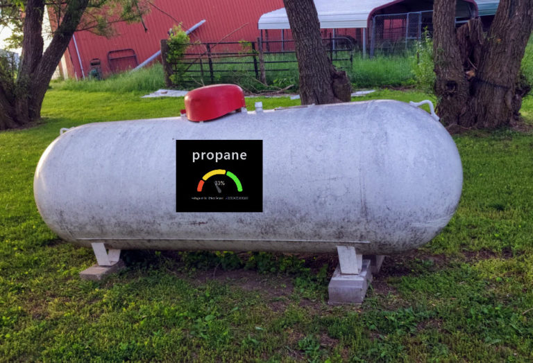
Given the success of my Remote Propane Gauge Project, which has been working beautifully in the field for more than a year, I wanted to build a similar sensor device that can determine what the approximate fill level is in the well tank, and then get that information over to Home Assistant.
From there, automations could be run to pause irrigation when the water supply falls below a certain level, or push notifications can be sent to my phone when the water supply is extremely low.
This post covers the hardware, the wiring, the sensor math, and the two Arduino sketches that run the whole thing. I’ll be honest about where it fought me — almost every problem turned out to be physical soldering problems, not code.
Here’s a video (fair warning, my soldering/wiring skills definitely won’t win any awards):
Situation
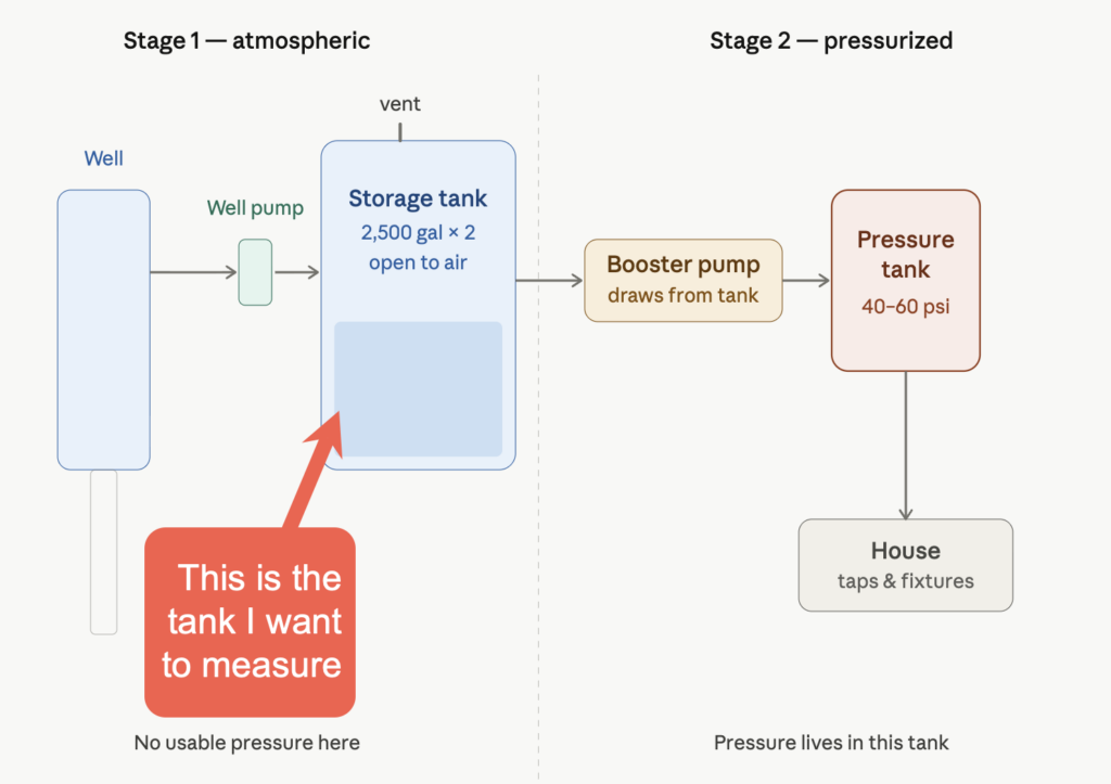
The wellhouse shed is across the street from the main house. There are two 2,500-gallon Norwesco water tanks that the well pump fills. The wellhouse has power, but no usable Wi-Fi. The main house has Wi-Fi, but the well house is a good 300+ feet away from the main house. That gap is exactly what LoRa is for: a low-power, tiny packet radio link that happily crosses a few hundred feet of trees and outbuildings where Wi-Fi gives up.
I know how to build basic ESP32 devices with simple circuits and sensors. But the way I saw it, I had two new problems to solve which I hadn’t tackled before.
First, I needed some way to measure water level, some kind of sensor which the ESP32 could read. And second, I needed to get those numbers over to the main house, but the home’s Wi-fi won’t reliably reach.
Regarding the sensor method, I turned to Claude.ai. It suggested that the two most common ways to measure water tank levels are either with an ultrasonic “distance” measurer (i.e., a proximity sensor, mounted in the tank, pointing down at the water level) or a “pressure-transducer probe.”
The ultrasonic distance measuring method is simple to set up and would have saved a ton of circuitry. All you do is mount a distance sensor in the lid, somehow, facing downward, and run the wires to your ESP32 board. But this is significantly less environmentally durable than a deepwater probe. Put simply, some people who have tried it say it suffers from a “leaf and spider web” problem in the wild. One tiny little adventurous spider, and your whole system reports “100% full” until you drive up there, open the tank, and fix it. (And yes, ew-yuk on spiders in the well water tank, but keep in mind that there are multiple levels of high-end filtration on this water AFTER it comes out of the holding tank and BEFORE it becomes potable water. Where do you think well water comes from?)
I decided instead to go with the pressure-transducer probe method.
The architecture
There are two boards, each running proprietary ESP32 code. I probably could have used Meshtastic or something, but that would be overkill.
I really just want to (1) Determine what the water level is, and (2) POST that onto MQTT so that Home Assistant can see it as “sensor entity.” This could have been done with one ESP32 board without LoRa if the well house were within reliable Wi-Fi range of the main house. But it isn’t.
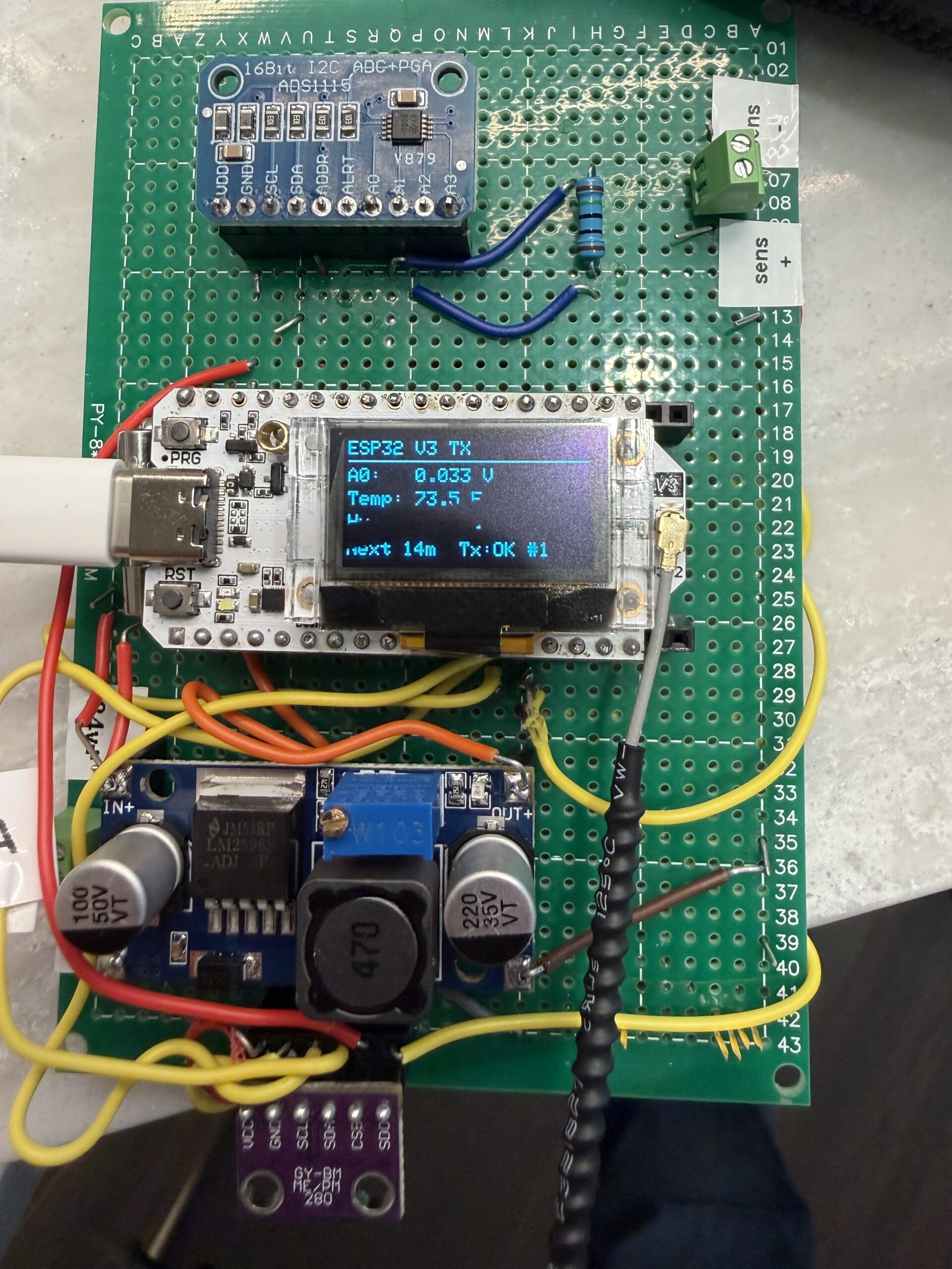
The ESP32 transmitter sits in the wellhouse. It reads the tank level – and a bonus, also reads temperature and humidity inside the wellhouse. The transmitter shows them on a small screen, and fires a LoRa packet to the house every 15 minutes. To save the OLED screen from burn-in, it also goes blank after blasting that packet (displaying only 15 seconds each time, though pressing the PRG button on the board can wake the screen.)
A receiver sits in the main house. It joins the home WiFi, listens for those packets from the wellhouse transmitter, and republishes every reading to MQTT, where any home dashboard such as Home Assistant or Node-RED can pick them up.
Both boards are the Heltec WiFi LoRa 32 V3, an ESP32-S3 with an onboard SX1262 radio, wifi, and a tiny OLED. At around $20 each, they bundle the microcontroller, radio, and display into one board, which removes most of the wiring guesswork. I’m still agog at what these little ESP32 boards can do.
Reading the tank: the part that matters most
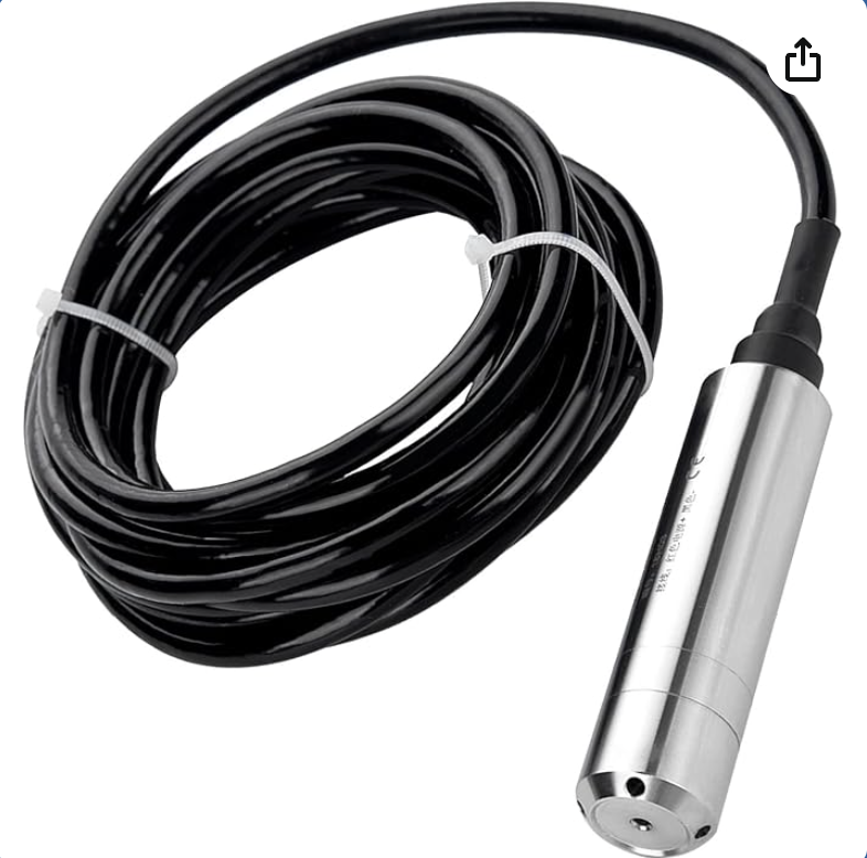
Tank level comes from a submersible pressure transducer, an ALS-MPM-2F rated 0 to 5 meters with a 4-20mA output. A “transducer” is just a nerdy name for a device that converts energy from one form to another.
Pressure transducers measure the pressure — i.e., the height of water above the probe tip, which is pure physics and does not care about the tank’s shape. That makes them ideal for level sensing. You have to make sure you don’t crimp the cable, because what the transducer is reading is the pressure differential between the outside world and the probe.
The catch with 4-20mA sensors as it relates to the ESP32 world is that they output current, not voltage, and a microcontroller’s analog input natively reads voltage.
So, you have to convert one to the other with a single sense resistor. Current flows through the resistor, and you measure the voltage across it. Specifically, with a 150-ohm resistor (which is what I used):
- 4mA (empty) produces 0.60V
- 20mA (full range) produces 3.00V
That range fits neatly inside the input window of an ADS1115, a 16-bit analog-to-digital converter that talks to the ESP32 over I2C and gives far better resolution than the ESP32’s own ADC.
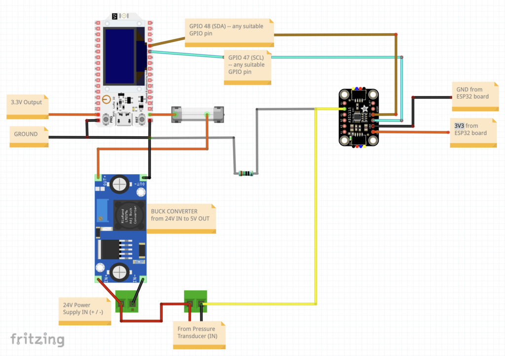
The loop is a series circuit. A 24V supply pushes current out, through the sensor, into the resistor, and back to the supply. (Note that you’ll also need to buy aa power cord for that supply. In the US at least, black is load, white is neutral, green is ground.)
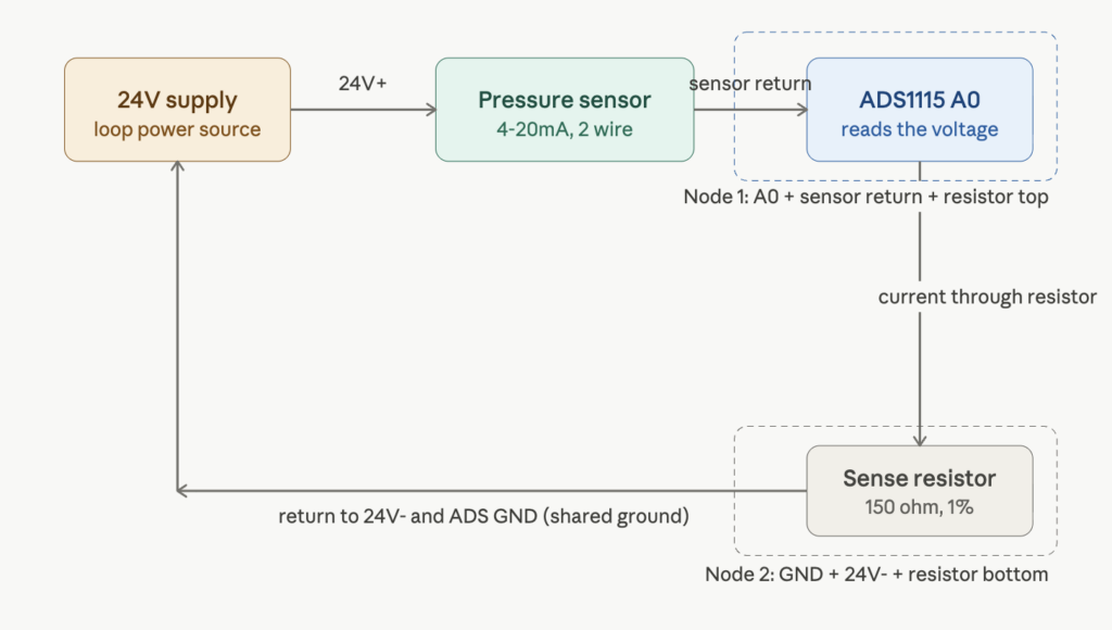
The single most important wiring fact, and the one that cost me a fuse, is that the resistor’s return end, the ADC ground, and the supply negative must all be the same node. Miss that connection and the current has no defined path home. Here is the topology (just a reiteration of the graphic above, but might be easier to follow):
SOURCE -> DESTINATION
24V(+) -> sensor(+) lead
sensor(-) lead -> ADS A0  +  sense resistor "top"      (NODE 1)
sense resistor "bottom" -> ADS GND  +  24V(-)          (NODE 2)
Code language: JavaScript (javascript)
Two nodes, the resistor bridges them, the sensor and supply complete the loop. Get that right, and you can read a clean voltage that tracks depth! Cool!
Basic circuit: (Some details like the humidity/temp sensor left off, just for clarity)
From voltage to gallons
The sensor gives depth. Turning depth into gallons is geometry, and a vertical cylinder is the easy case because every inch of height holds the same volume. The Norwesco 40631 is 95 inches in diameter, so:
- Radius 47.5 inches, area = pi x 47.5^2 = 7,088 square inches
- Volume per inch = 7,088 cubic inches, or about 30.7 gallons per inch (231 cubic inches per gallon)
So depth in inches times 30.7 gives gallons, clamped at the tank’s practical full. The calibration in code uses two points, an empty reading and a known level, so it absorbs the sensor’s real-world offset rather than trusting the theoretical 4mA zero. After install, you read the empty-tank voltage off the serial monitor and drop it into one constant. That single trim handles the only meaningful drift.
The LoRa link
LoRa point-to-point is refreshingly simple once both radios agree on their parameters. The two boards must share frequency, bandwidth, spreading factor, coding rate, and sync word exactly, or they sit silent with no error and no packets. I used 915 MHz (the legal ISM band in the US), 125 kHz bandwidth, spreading factor 9. RadioLib drives the SX1262 and handles the rest.
The payload is a short comma-separated string:
G=553,P=24,V=1.400,T=72.5,H=45.2
Gallons, percent, raw voltage, temperature, humidity. I deliberately include the raw voltage so all the level math can live on the receiver side, in the house, where it is easy to recalibrate without ever reflashing the board sitting out at the tank.
BEFORE YOU GET THE SOLDERING IRON OUT — SOME WARNINGS. There are three easy ways to make “magic smoke” and permanently destroy the ESP32 board:
WARNING #1: CONNECT THE ANTENNA before powering up! If you make that mistake, it can fry the board, because the power for the signal needs to go somewhere, and if you don’t give it an antenna, it can basically burn the board out.
WARNING #2: Do not ever power your ESP32 board with both the USB-C connector and the buck converter from the 24V power supply at the same time! Always choose EITHER one or the other.
WARNING #3: Most variable buck converters, such as the one I show in the video, are set to HIGHEST voltage by default. Output voltage is altered by turning that brass screw counterclockwise a LOT (with a multimeter probing the output.) Use a multimeter to pre-calibrate the buck converter to output 5V BEFORE you wire it in to the ESP32 inputs. Do not wire your ESP32 board into the buck converter without first using a multimeter to trim-down the variable buck converter to 5V!
Amazingly, I didn’t do any of these (yet!) — but I did make many mistakes soldering that had to be corrected. This was a skill issue on my part, translating the paper diagram to a soldered board.
Mistakes I made included:
- In the first iteration, I directly wired the header pins of an ESP32 to the board itself! Duh, ALWAYS USE HEADERS.
- I should also have used double headers for the ADS1115 device! It’s so much easier to just take two 8-pin female headers and join them on a through-hole board than it is to connect wires.
- Headers are your friend! I’ll be sure to use them liberally for my next wiring project.
- It was on this project that I realized just how useful an audible continuity detector is! Most multimeters can go into “continuity” mode, where, when you tap the probes on two contacts, it will beep if there’s a connection between these items. So, with the power off on your board, tap various GND terminals together — all pairs should beep. Your entire ground circuit should run back to one of the ESP32’s ground leads.
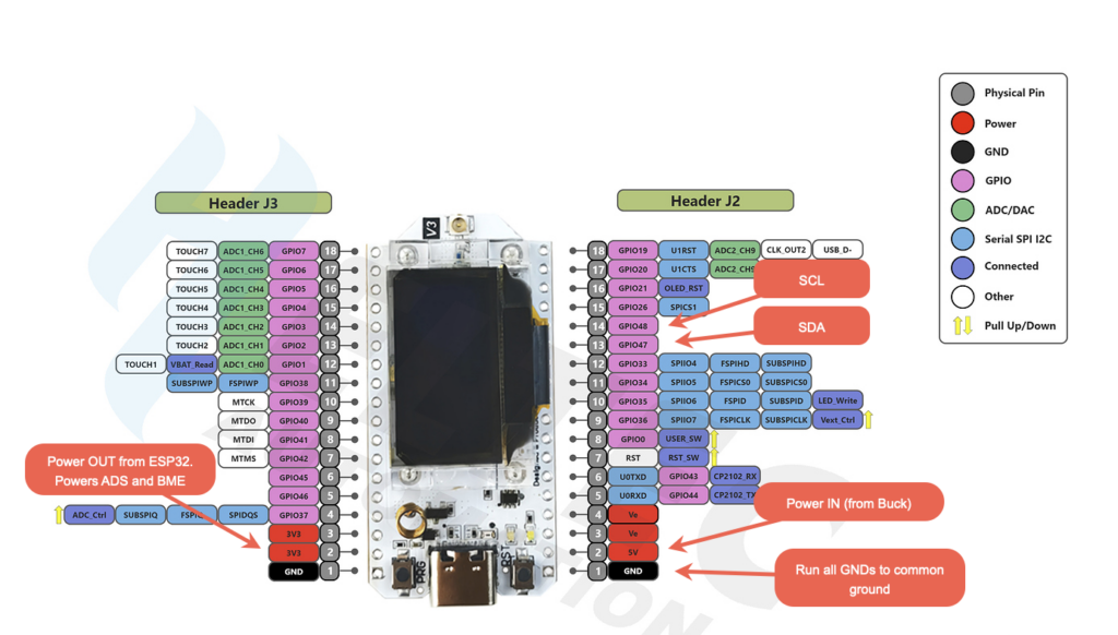
- USE THE CORRECT PINOUT SHEET! The v3 ESP32 board from Heltec without LoRa and the v3 ESP32 board WITH LoRa have very different pinout numbers! I wasted a full day on this particular mistake, but miraculously didn’t fry the board.
- Fun tip: You can ask Claude (I can’t vouch for other LLM’s on this) to give you a list of pin pairs to probe with your multimeter (with the board unpowered) and whether they should beep or not. Claude will give you a nice table. Super handy double-check before you apply power!
I2C
This was my first project wiring in multiple I2C devices. I used to find I2C a scary concept, thinking if I did it wrong, I’d short something out, but it’s really quite simple. It’s just a “bus” communication protocol that uses 4 wires, and multiple I2C compatible sensors can (and often should) share the same bus.
Most ESP32 boards can support a couple I2C busses; this one has a dedicated I2C bus for the OLED display that you really shouldn’t mess with. Generally things like OLED screens should live on their own bus, because crowding that with other messages and readings can disrupt the display.
The 4 wires of I2C are: 3.3V, GND, SCL, and SDA. The 3.3V and GND are obvious enough… the SCL is a “clock” wire, and the SDA is the “data” wire.
You basically daisy chain the sensors to the SCL and SDA wire, and send all the GNDs to your common ground line, and give them power on the 3.3V in side. That’s it! If you are only using one sensor type per project, it will be burned in with an address, and 99% likely it will not conflict. (Some sensors have an ADDR pin that can be driven high or low to change the address to some unique value. ALL I2C devices must have a unique address.) I suggest running the standard I2C scanner code on your microcontroller to ensure it “sees” all the I2C devices. In this project, on the transmitter, there are 3 I2C devices: the OLED display on one bus, and the BME280 (temp/humidity sensor) and the ADS1115 (analog to digital converter) on the other bus.
Saving the screens from burn-in over time
Both boards have OLED displays, and OLEDs burn in if you leave a static layout lit 24/7. The fix is to keep them dark by default. The transmitter wakes its screen for 15 seconds after each transmission, the receiver for 15 seconds after each packet. Pressing the onboard PRG button wakes either screen for 15 minutes. The receiver also forces its screen on, and refuses to blank it, whenever WiFi or MQTT drops, because a connection problem is exactly when you walk over to look. That turns a months-to-burn-in risk into a roughly 2 percent duty cycle.
One small touch: my transmitter is mounted upside down in its enclosure, so a single line flipped the display 180 degrees in software.
Where it fought me
The system worked on paper long before it worked on the bench, and every failure of mine was physical, related to the soldering.
First reading was a flat 0.03V that ignored the water. Cause: I had powered the logic from USB while the analog side expected its ground reference from the buck converter, so the input floated. Duh. The probe needs 24V, not the normal USB 5V. (AGAIN, DO NOT RUN POWER FROM BOTH THE 24V SUPPLY AND USB-C INTO THE ESP32, EVER! IT WILL FRY THE BOARD.)
Then, no sensor appeared on the I2C bus at all. Cause: swapped SDA and SCL wires. An I2C scanner sketch found it in seconds once I stopped assuming and started measuring.
Then a soldered fuse glowed. Cause: the 4-20mA loop was missing the resistor’s return path to the supply negative, so the current found a path that bypassed the sense resistor entirely, effectively a short.
Then a dead power rail that looked like a short but passed every continuity test. Cause: a fault that only conducted under load, isolated by disconnecting the buck output one wire at a time until the supply came back.
The lesson, if there is one: when a circuit misbehaves, measure the physical connections before you suspect the code. A multimeter in continuity mode found every one of these faults.
I worked through the debugging with an AI assistant, which was really useful for the methodical isolate-and-test sequences.
The code
The full transmitter and receiver sketches are below. They target the Arduino IDE with the Heltec V3 board package and rely on RadioLib, the Adafruit ADS1X15, BME280, SSD1306 and GFX libraries, and PubSubClient for MQTT. Drop in your own WiFi and broker details at the top of the receiver, flash the receiver first so it is listening, then the transmitter, which sends one packet at boot so you do not wait 15 minutes to confirm the link.
Transmitter
/*
 * Heltec WiFi LoRa 32 V3 - TANK MONITOR TRANSMITTER
 * ---------------------------------------------------------------
 * Norwesco 40631 tank (95" dia x 91" tall vertical cylinder).
 * Water level via ALS-MPM-2F 2-wire 4-20mA submersible probe
 * (0-5m / 0-197in range) on ADS1115 A0 with a 150 ohm sense
 * resistor, plus BME280 temp/humidity. LoRa every 15 min.
 *
 * DISPLAY POWER MANAGEMENT (to protect the OLED from 24/7 burn-in):
 *   - Screen is OFF by default.
 *   - Wakes for 15 SECONDS after each LoRa send.
 *   - PRG button (GPIO0) press wakes it for 15 MINUTES.
 *   - Longer timer wins if they overlap.
 *   LoRa transmission runs regardless of screen state.
 *
 * Buses:
 *   OLED    0x3C  on Wire  (SDA 17, SCL 18)
 *   ADS1115 0x48  on Wire1 (SDA 47, SCL 48)
 *   BME280  0x76  on Wire1 (SDA 47, SCL 48)
 *
 * LoRa payload: G=553,P=24,V=1.400,T=72.5,H=45.2
 *   G = gallons, P = percent, V = raw A0 volts, T = temp F, H = humidity %
 *
 * Libraries: RadioLib, Adafruit ADS1X15, Adafruit BME280,
 *            Adafruit SSD1306, Adafruit GFX
 * Board: "Heltec WiFi LoRa 32(V3)"
 */

#include <Wire.h>
#include <Adafruit_GFX.h>
#include <Adafruit_SSD1306.h>
#include <Adafruit_ADS1X15.h>
#include <Adafruit_BME280.h>
#include <RadioLib.h>

// ---- OLED bus ----
#define OLED_SDA    17
#define OLED_SCL    18
#define OLED_RST    21
#define VEXT_CTRL   36          // LOW = enable peripheral power rail
#define OLED_ADDR   0x3C
#define SCREEN_W    128
#define SCREEN_H    64

// ---- Sensor bus ----
#define SENSOR_SDA  47
#define SENSOR_SCL  48
#define ADS_ADDR    0x48
#define BME_ADDR    0x76

// ---- SX1262 radio pins (Heltec V3) ----
#define LORA_NSS     8
#define LORA_DIO1   14
#define LORA_RST    12
#define LORA_BUSY   13

// ---- User button (onboard PRG, active LOW) ----
#define USER_BTN     0

// ---- Radio settings (MUST match receiver) ----
#define LORA_FREQ   915.0       // MHz (US/Americas)
#define LORA_BW     125.0       // kHz
#define LORA_SF     9
#define LORA_CR     7
#define LORA_SYNC   0x34
#define LORA_PWR    14          // dBm

// ---- Display on-times ----
const unsigned long DISP_SEND_MS = 15UL * 1000UL;        // 15 s after a send
const unsigned long DISP_BTN_MS  = 15UL * 60UL * 1000UL; // 15 min on button

// ===== Tank level calibration: ALS-MPM-2F, 0-5m/197in, 4-20mA =====
// Probe on tank floor: reading-inches = water depth above probe.
// Theoretical 4-20mA mapping on a 150 ohm sense resistor:
//   4 mA  -> 0.600 V -> 0 in    (empty)
//   20 mA -> 3.000 V -> 197 in  (full range)
// TO REFINE AFTER INSTALL:
//   1) With water at/near the probe tip, read A0 volts from Serial.
//      Put that value in CAL_V1 (true empty / 4mA point).
//   2) At a known higher level (tape-measured), put that volts/inches
//      pair in CAL_V2 / CAL_IN2. Two real points beat the theoretical.
const float CAL_V1 = 0.600, CAL_IN1 = 0.0;     // 4 mA, empty
const float CAL_V2 = 3.000, CAL_IN2 = 197.0;   // 20 mA, full range
const float GAL_PER_INCH = 30.7;        // pi*(47.5^2)/231, vertical cylinder
const float TANK_MAX_GAL = 2300.0;      // practical full
// ==================================================================

// ---- Timing ----
const unsigned long SEND_INTERVAL_MS = 15UL * 60UL * 1000UL;  // 15 minutes

Adafruit_SSD1306 display(SCREEN_W, SCREEN_H, &Wire, OLED_RST);
Adafruit_ADS1115 ads;
Adafruit_BME280  bme;
SX1262 radio = new Module(LORA_NSS, LORA_DIO1, LORA_RST, LORA_BUSY);

bool adsOK = false, bmeOK = false, radioOK = false;
unsigned long lastSend = 0;
unsigned long lastTxCount = 0;
String lastTxStatus = "none";

// ---- Display state ----
bool displayOn = false;
unsigned long displayOffAt = 0;   // millis() when the screen should turn off

// ---- Level conversion ----
float voltsToInches(float volts) {
  float slope = (CAL_IN2 - CAL_IN1) / (CAL_V2 - CAL_V1);
  float inches = CAL_IN1 + (volts - CAL_V1) * slope;
  if (inches < 0) inches = 0;
  return inches;
}
float inchesToGallons(float inches) {
  float g = inches * GAL_PER_INCH;
  if (g > TANK_MAX_GAL) g = TANK_MAX_GAL;
  return g;
}
float gallonsToPercent(float gal) { return (gal / TANK_MAX_GAL) * 100.0; }

// ---- Display power helpers ----
// Wake for at least 'durationMs'. If already on for longer, keep the longer time.
void wakeDisplay(unsigned long durationMs) {
  unsigned long newOffAt = millis() + durationMs;
  if (!displayOn) {
    display.ssd1306_command(SSD1306_DISPLAYON);
    displayOn = true;
    displayOffAt = newOffAt;
  } else if (newOffAt > displayOffAt) {
    displayOffAt = newOffAt;  // extend, never shorten
  }
}
void sleepDisplay() {
  display.ssd1306_command(SSD1306_DISPLAYOFF);
  displayOn = false;
}

void setup() {
  Serial.begin(115200);
  delay(500);

  pinMode(USER_BTN, INPUT_PULLUP);

  pinMode(VEXT_CTRL, OUTPUT);
  digitalWrite(VEXT_CTRL, LOW);
  delay(50);
  pinMode(OLED_RST, OUTPUT);
  digitalWrite(OLED_RST, LOW);  delay(20);
  digitalWrite(OLED_RST, HIGH); delay(20);

  Wire.begin(OLED_SDA, OLED_SCL);
  Wire1.begin(SENSOR_SDA, SENSOR_SCL);

  if (!display.begin(SSD1306_SWITCHCAPVCC, OLED_ADDR)) {
    Serial.println("OLED init failed");
    while (true) delay(100);
  }
  display.setRotation(2);   // 180 deg: enclosure mounts the board upside down
  display.clearDisplay();
  display.setTextColor(SSD1306_WHITE);
  display.setTextSize(1);
  display.setCursor(0, 0);
  display.println("Tank TX starting...");
  display.display();
  wakeDisplay(DISP_SEND_MS);   // show boot message briefly

  if (ads.begin(ADS_ADDR, &Wire1)) { ads.setGain(GAIN_ONE); adsOK = true; }  // +/-4.096V
  else Serial.println("ADS1115 not found");

  if (bme.begin(BME_ADDR, &Wire1)) bmeOK = true;
  else Serial.println("BME280 not found");

  Serial.print("Radio init... ");
  int st = radio.begin(LORA_FREQ, LORA_BW, LORA_SF, LORA_CR, LORA_SYNC, LORA_PWR);
  if (st == RADIOLIB_ERR_NONE) { radioOK = true; Serial.println("OK"); }
  else Serial.printf("failed, code %d\n", st);

  // Transmit once immediately at boot, then every 15 min.
  lastSend = millis() - SEND_INTERVAL_MS;
}

void transmitReadings(float gal, float pct, float volts, float tempF, float hum) {
  char payload[80];
  snprintf(payload, sizeof(payload), "G=%.0f,P=%.0f,V=%.3f,T=%.1f,H=%.1f",
           gal, pct, volts, tempF, hum);
  Serial.printf("TX -> %s ... ", payload);
  int st = radio.transmit(payload);
  if (st == RADIOLIB_ERR_NONE) {
    lastTxCount++;
    lastTxStatus = "OK #" + String(lastTxCount);
    Serial.println("sent");
  } else {
    lastTxStatus = "ERR " + String(st);
    Serial.printf("failed, code %d\n", st);
  }
}

void loop() {
  // --- Button: PRG press wakes display for 15 minutes (active LOW) ---
  if (digitalRead(USER_BTN) == LOW) {
    wakeDisplay(DISP_BTN_MS);
    delay(200);   // simple debounce
  }

  // --- Read sensors ---
  float volts = 0, inches = 0, gal = 0, pct = 0, tempF = 0, hum = 0;
  if (adsOK) {
    volts  = ads.computeVolts(ads.readADC_SingleEnded(0));
    inches = voltsToInches(volts);
    gal    = inchesToGallons(inches);
    pct    = gallonsToPercent(gal);
  }
  if (bmeOK) {
    tempF = bme.readTemperature() * 9.0 / 5.0 + 32.0;
    hum   = bme.readHumidity();
  }

  // --- Transmit on schedule, then wake screen for 15 s ---
  if (radioOK && (millis() - lastSend >= SEND_INTERVAL_MS)) {
    transmitReadings(gal, pct, volts, tempF, hum);
    lastSend = millis();
    wakeDisplay(DISP_SEND_MS);
  }

  // --- Serial echo (also use this to read raw volts for calibration) ---
  Serial.printf("Lvl: %.0f gal (%.0f%%, %.1f in, %.3f V)  T:%.1fF  H:%.1f%%\n",
                gal, pct, inches, volts, tempF, hum);

  // --- Auto-sleep when the on-timer expires ---
  if (displayOn && (long)(millis() - displayOffAt) >= 0) {
    sleepDisplay();
  }

  // --- Draw only while the screen is on ---
  if (displayOn) {
    long remain = (long)SEND_INTERVAL_MS - (long)(millis() - lastSend);
    if (remain < 0) remain = 0;
    unsigned long minsToNext = remain / 60000UL;

    display.clearDisplay();
    display.setTextSize(1);
    display.setCursor(0, 0);
    display.println("TANK MONITOR");
    display.drawLine(0, 10, SCREEN_W - 1, 10, SSD1306_WHITE);

    display.setCursor(0, 14);
    if (adsOK) display.printf("%.0f gal  %.0f%%", gal, pct);
    else       display.print("level: no ADS");

    display.setCursor(0, 26);
    if (bmeOK) display.printf("Temp: %.1f F", tempF); else display.print("Temp: no BME");
    display.setCursor(0, 38);
    if (bmeOK) display.printf("Hum:  %.1f %%", hum);  else display.print("Hum:  no BME");

    display.setCursor(0, 52);
    if (radioOK) display.printf("Next %lum  %s", minsToNext, lastTxStatus.c_str());
    else         display.print("RADIO FAIL");

    display.display();
  }

  delay(50);   // short loop keeps the button responsive
}
Code language: PHP (php)
Receiver
/*
 * Heltec WiFi LoRa 32 V3 - TANK RECEIVER -> WiFi -> MQTT
 * ---------------------------------------------------------------
 * Listens for the tank transmitter's LoRa payload, parses it,
 * shows it on the OLED, and publishes each value to an MQTT broker.
 *
 * Expected LoRa payload: G=553,P=24,V=1.400,T=72.5,H=45.2
 *   G = gallons, P = percent, V = raw A0 volts, T = temp F, H = humidity %
 *
 * Libraries: RadioLib, PubSubClient, Adafruit SSD1306, Adafruit GFX
 *            (WiFi is built into the ESP32 core)
 * Board: "Heltec WiFi LoRa 32(V3)"
 *
 * Radio settings MUST match the transmitter exactly.
 */

#include <Wire.h>
#include <WiFi.h>
#include <PubSubClient.h>
#include <Adafruit_GFX.h>
#include <Adafruit_SSD1306.h>
#include <RadioLib.h>

// =====================================================================
//  CONFIG - FILL THESE IN
// =====================================================================
const char* WIFI_SSID     = "YOUR_SSID";
const char* WIFI_PASSWORD = "YOUR_PASSWORD";

const char* MQTT_HOST      = "192.168.1.100";   // broker IP or hostname
const int   MQTT_PORT      = 1883;
const char* MQTT_USER      = "";                // "" if no auth
const char* MQTT_PASS      = "";                // "" if no auth
const char* MQTT_CLIENT_ID = "tank-monitor-rx"; // unique on the broker

// MQTT topics
const char* TOPIC_GALLONS = "tank/gallons";
const char* TOPIC_PERCENT = "tank/percent";
const char* TOPIC_VOLTS   = "tank/raw_voltage";
const char* TOPIC_TEMP_F  = "tank/temperature_f";
const char* TOPIC_HUMID   = "tank/humidity";
const char* TOPIC_RSSI    = "tank/rssi";
const char* TOPIC_SNR     = "tank/snr";
const char* TOPIC_JSON    = "tank/state";       // combined JSON
// =====================================================================

// ---- OLED bus ----
#define OLED_SDA    17
#define OLED_SCL    18
#define OLED_RST    21
#define VEXT_CTRL   36
#define OLED_ADDR   0x3C
#define SCREEN_W    128
#define SCREEN_H    64

// ---- SX1262 radio pins (Heltec V3) ----
#define LORA_NSS     8
#define LORA_DIO1   14
#define LORA_RST    12
#define LORA_BUSY   13

// ---- Radio settings (MUST match transmitter) ----
#define LORA_FREQ   915.0
#define LORA_BW     125.0
#define LORA_SF     9
#define LORA_CR     7
#define LORA_SYNC   0x34
#define LORA_PWR    14

Adafruit_SSD1306 display(SCREEN_W, SCREEN_H, &Wire, OLED_RST);
SX1262 radio = new Module(LORA_NSS, LORA_DIO1, LORA_RST, LORA_BUSY);
WiFiClient   wifiClient;
PubSubClient mqtt(wifiClient);

volatile bool packetFlag = false;
unsigned long pktCount = 0;

float rxGal = 0, rxPct = 0, rxVolts = 0, rxTempF = 0, rxHum = 0;
float lastRSSI = 0, lastSNR = 0;
bool  haveData = false;

ICACHE_RAM_ATTR void onReceive() { packetFlag = true; }

void connectWiFi() {
  if (WiFi.status() == WL_CONNECTED) return;
  Serial.printf("WiFi connecting to %s ...\n", WIFI_SSID);
  WiFi.mode(WIFI_STA);
  WiFi.begin(WIFI_SSID, WIFI_PASSWORD);
  unsigned long start = millis();
  while (WiFi.status() != WL_CONNECTED && millis() - start < 15000) {
    delay(250); Serial.print(".");
  }
  if (WiFi.status() == WL_CONNECTED)
    Serial.printf("\nWiFi OK, IP %s\n", WiFi.localIP().toString().c_str());
  else
    Serial.println("\nWiFi FAILED (will retry)");
}

void connectMQTT() {
  if (mqtt.connected()) return;
  mqtt.setServer(MQTT_HOST, MQTT_PORT);
  Serial.printf("MQTT connecting to %s:%d ...\n", MQTT_HOST, MQTT_PORT);
  bool ok = (strlen(MQTT_USER) > 0)
            ? mqtt.connect(MQTT_CLIENT_ID, MQTT_USER, MQTT_PASS)
            : mqtt.connect(MQTT_CLIENT_ID);
  Serial.println(ok ? "MQTT OK" : "MQTT failed (will retry)");
}

void publishReadings() {
  if (!mqtt.connected()) return;
  char buf[24];
  snprintf(buf, sizeof(buf), "%.0f", rxGal);   mqtt.publish(TOPIC_GALLONS, buf, true);
  snprintf(buf, sizeof(buf), "%.0f", rxPct);   mqtt.publish(TOPIC_PERCENT, buf, true);
  snprintf(buf, sizeof(buf), "%.3f", rxVolts); mqtt.publish(TOPIC_VOLTS,   buf, true);
  snprintf(buf, sizeof(buf), "%.1f", rxTempF); mqtt.publish(TOPIC_TEMP_F,  buf, true);
  snprintf(buf, sizeof(buf), "%.1f", rxHum);   mqtt.publish(TOPIC_HUMID,   buf, true);
  snprintf(buf, sizeof(buf), "%.0f", lastRSSI);mqtt.publish(TOPIC_RSSI,    buf, true);
  snprintf(buf, sizeof(buf), "%.1f", lastSNR); mqtt.publish(TOPIC_SNR,     buf, true);

  char json[200];
  snprintf(json, sizeof(json),
    "{\"gallons\":%.0f,\"percent\":%.0f,\"raw_voltage\":%.3f,"
    "\"temperature_f\":%.1f,\"humidity\":%.1f,\"rssi\":%.0f,\"snr\":%.1f,\"pkt\":%lu}",
    rxGal, rxPct, rxVolts, rxTempF, rxHum, lastRSSI, lastSNR, pktCount);
  mqtt.publish(TOPIC_JSON, json, true);
  Serial.printf("MQTT published: %s\n", json);
}

void parsePayload(const String &s) {
  // G=553,P=24,V=1.400,T=72.5,H=45.2
  int g = s.indexOf("G=");
  int p = s.indexOf("P=");
  int v = s.indexOf("V=");
  int t = s.indexOf("T=");
  int h = s.indexOf("H=");
  if (g >= 0) rxGal   = s.substring(g + 2, s.indexOf(',', g)).toFloat();
  if (p >= 0) rxPct   = s.substring(p + 2, s.indexOf(',', p)).toFloat();
  if (v >= 0) rxVolts = s.substring(v + 2, s.indexOf(',', v)).toFloat();
  if (t >= 0) rxTempF = s.substring(t + 2, s.indexOf(',', t)).toFloat();
  if (h >= 0) rxHum   = s.substring(h + 2).toFloat();
  haveData = true;
}

void drawScreen(const char* statusLine) {
  display.clearDisplay();
  display.setTextSize(1);
  display.setCursor(0, 0);
  display.println("TANK RX -> MQTT");
  display.drawLine(0, 10, SCREEN_W - 1, 10, SSD1306_WHITE);

  if (haveData) {
    display.setCursor(0, 14); display.printf("%.0f gal  %.0f%%", rxGal, rxPct);
    display.setCursor(0, 26); display.printf("Temp: %.1f F", rxTempF);
    display.setCursor(0, 38); display.printf("Hum:  %.1f %%", rxHum);
    display.setCursor(0, 52);
    bool w = (WiFi.status() == WL_CONNECTED), m = mqtt.connected();
    display.printf("#%lu W%c M%c R%d", pktCount, w?'+':'-', m?'+':'-', (int)lastRSSI);
  } else {
    display.setCursor(0, 24); display.println(statusLine);
    display.setCursor(0, 40);
    display.printf("WiFi:%s MQTT:%s",
      (WiFi.status()==WL_CONNECTED)?"up":"--", mqtt.connected()?"up":"--");
  }
  display.display();
}

void setup() {
  Serial.begin(115200);
  delay(500);

  pinMode(VEXT_CTRL, OUTPUT);
  digitalWrite(VEXT_CTRL, LOW);
  delay(50);
  pinMode(OLED_RST, OUTPUT);
  digitalWrite(OLED_RST, LOW);  delay(20);
  digitalWrite(OLED_RST, HIGH); delay(20);

  Wire.begin(OLED_SDA, OLED_SCL);

  if (!display.begin(SSD1306_SWITCHCAPVCC, OLED_ADDR)) {
    Serial.println("OLED init failed");
    while (true) delay(100);
  }
  display.setTextColor(SSD1306_WHITE);
  drawScreen("Booting...");

  connectWiFi();
  connectMQTT();

  Serial.print("Radio init... ");
  int st = radio.begin(LORA_FREQ, LORA_BW, LORA_SF, LORA_CR, LORA_SYNC, LORA_PWR);
  if (st != RADIOLIB_ERR_NONE) {
    Serial.printf("failed, code %d\n", st);
    drawScreen("RADIO FAIL");
    while (true) delay(100);
  }
  Serial.println("OK");

  radio.setPacketReceivedAction(onReceive);
  radio.startReceive();
  drawScreen("Listening...");
}

void loop() {
  if (WiFi.status() != WL_CONNECTED) connectWiFi();
  if (!mqtt.connected()) connectMQTT();
  mqtt.loop();

  if (packetFlag) {
    packetFlag = false;
    String str;
    int st = radio.readData(str);
    if (st == RADIOLIB_ERR_NONE) {
      pktCount++;
      lastRSSI = radio.getRSSI();
      lastSNR  = radio.getSNR();
      Serial.printf("RX: %s | RSSI %.0f | SNR %.1f\n", str.c_str(), lastRSSI, lastSNR);
      parsePayload(str);
      publishReadings();
      drawScreen("");
    } else {
      Serial.printf("RX error, code %d\n", st);
    }
    radio.startReceive();
  }
}
Code language: PHP (php)
What’s next
So, as I write this, the whole transmitter – receiver thing is working great, and actually changes values appropriately when the probe is inserted into test water (a bathtub.) The deeper the probe sites, the higher the voltage the A0 pin on the ADS1115 reports.
The next steps will be to take it to the property and install it at the well house and into the tank. Then, the receiver needs to simply have the wifi and MQTT server details to connect to the home wifi, and then be plugged in.
From there, Home Assistant can pick up MQTT values (which persist by default) and do things with them — chart them, log them, create automations or alerts based on them, pause irrigation when below a certain value, etc.
At a minimum, I’d like an alert that fires when the tank drops below a threshold, and a stale-data warning for when the transmitter goes quiet, are the obvious additions. Both are a few lines.
Soon, I can glance at a dashboard in the house and know exactly how much water is in a tank a few hundred feet away, and even fully remotely via the Home Assistant app, which is precisely what I set out to do. ESP32 devices are super cheap, and really useful with some programming!
Related post: Read Propane Levels from Anywhere with Home Assistant and an ESP32


